 Why Subnetting ? When there is a network with a size large, it may sound fine but it gets to a stage when that network performance starts to suffer due to too much traffic. One of the most effective solutions to the problem just mentioned here is breaking the network into smaller sizes by the technique of subnetting. What is subnetting? Subnetting is the technique of segmenting a TCP / IP network into manageable sizes that are smaller. Too much traffic on a single network would slow the network down. Therefore subnetting a large network is breaking it up into smaller separate yet interconnected network. This isolates most traffic to its originating subnet. This however does not stop communication between subnets as they are interconnected but will be limited to when the destination host is on a different subnet to the source / originating subnet. Firstly, there should be some sort of planning for each subnet in terms of size of the network, number of hosts required and number of subnets required. Subnets could also be planned based on various circumstances such as users within a department. We will discuss planning in details later. The purpose of subnetting is defeated if multiple subnets share a common hub. Before we proceed, we need to know our 2 to the power of n (n is the number of host bits). However, we will concern ourselves with only 1-8 i.e.  We also need to remind ourselves that each octet has 8 bits each. Each bit is indicated in the prefix of the subnet mask. If for example we use 192 . 160 . 1 . 0/24 with default subnet mask 255 . 255 . 255 . 0, its prefix is /24 meaning that the first 24 bits (the first 3 octets) is the network portion. This subnet mask table will come in handy in our calculations. Formula to calculate number of usable hosts = 2 to the power of n – 2 (n is the number of host bits remaining after bits are borrowed). 2 is subtracted because 2 addresses must be reserved always for the Network address and Broadcast address respectively. If we borrow 1 bit from the host portion, we will create 2 subnets. Thus 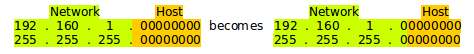 The subnets now have addresses as follows 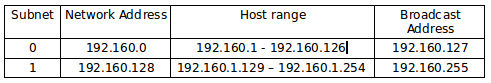 Are you wondering how I arrived at the new address and subnet mask ? Well ! How many bits did we borrow? 1 (8 host bits – 1 borrowed bit = 7 bits left for hosts) How many subnets were thus created? (2 to the power of 1) = 2 subnets How many usable hosts per subnet? (2 to the power of 7) - 2 = 126 i.e (128 – 2 = 126) What is the new subnet mask? 255 . 255 . 255 . 128 What is the block size? 256 – 128 = 128 => Block size = 256 – value of octet in subnet mask If we borrow 2 bits, we will create 4 subnets.  The subnets now have addresses as follows 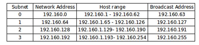  How to work out the 4 subnets  Are you wondering how I arrived at the new address and subnet mask too? Well ! How many bits did we borrow? 2 How many subnets were thus created? (2 to the power of 2) = 4 subnets How many usable hosts per subnet? (2 to the power of 6) - 2 = 62 i.e (64 – 2 = 62) What is the new subnet mask? 255 . 255 . 255 . 192 number of hosts required What is the block size? 256 – 192= 64 => =>Block size = 256 – value of octet in subnet mask If we borrow 3 bits, we will create 8 subnets.  The subnets now have addresses as follows 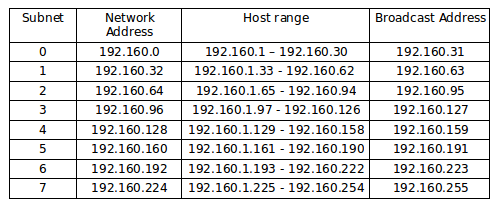  How to work out the 8 subnets  Are you still wondering how I arrived at the new address and subnet mask too? Well !
How many bits did we borrow? 3 How many subnets were thus created? (2 to the power of 3) = 8 subnets How many usable hosts per subnet? (2 to the power of 5) - 2 = 30 i.e (32 – 2 = 30) What is the new subnet mask? 255 . 255 . 255 . 224 What is the block size? 256 – 224= 32 => Block size = 256 – value of octet in subnet mask References http://searchnetworking.techtarget.com/feature/Subnetting-to-increase-performance https://www.cisco.com/c/en/us/support/docs/ip/routing-information-protocol-rip/13788-3.htm This means communicating with a device on a different network. As discussed previously, an IP address consists of 2 parts. The 1st part indicative of the network which the IP address belongs and the 2nd indicative of the host. When a packet is sent from one network to another, the IP address will clearly show that they are of different networks. Example: IP address of the sending device (source IP address) – 192.168.1.110 (PC1) IP address of the receiving device (destination IP address) – 172.16.1.99 (Web Server) 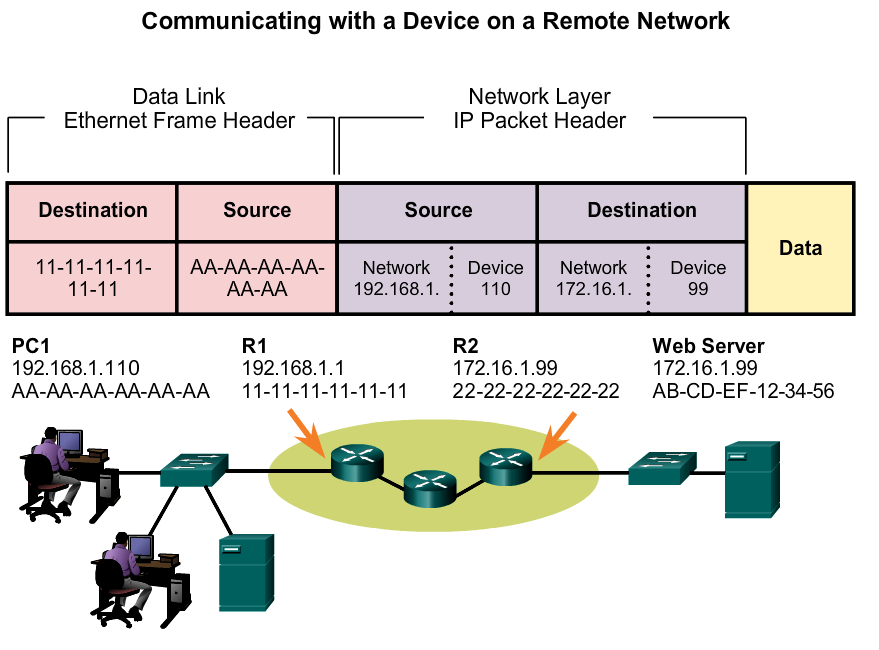 Whenever a message (packet) is being sent from one network to another network, the packet cannot go directly to the destination device because it is in a different network from the sender. The message leaves the source network through the default gateway of the source network - the final exit from the source network and usually on a router. It then travels through and received by other routers or the router at the entrance into the destination network. This router at the entrance of the destination network will have the default gateway into the destination network. The default gateway of the destination network is the entrance into that network. This last router de-encapsulates the packet translating it into a frame (as discussed previously). The network address and the Mac address come into play when sending packets across different networks. Each device will know the IP address of its default gateway among other settings. The default gateway address of the source device is the IP address of the router interface connected to the same local network as the source device while the default gateway address of the destination device is the address of the router interface connected to the same local network as the destination device device. The MAC address of the sending device (source) in this example, PC1 is AA-AA-AA-AA-AA-AA. However the destination MAC address when the receiving device is on a different network from the source will be the MAC address of the default gateway or router. For this purpose, the MAC address of the R1 Ethernet interface – 11-11-11-11-11-11, which is connected to the PC1 network is the destination MAC address. The packet is received on R1 from the source device. R1 sends the packet to its destination which is the Web Server. However for this particular example, there are a couple of routers between R1 and the destination device. Once the IP address of the default gateway is known, ARP (as discussed in the last topic) will come into play, to establish the MAC address of that default gateway which is then added to the frame. References http://paf.dias.ac.cy/main/files/cisco_rs_ite/CCNA-R-S_ITN/course/module3/3.3.3.2/3.3.3.2.html IP addressing occurs both on layers 2 and 3 of the OSI model. Layer 2 IP addressing is used for local transmission – directly connected and / or within the same network which does not involve a router. Layer 3 IP addressing is used for devices not directly connected in an inter-networking environment or remotely and involves a router. Devices on the same network communicate using a discovery protocol called Address Resolution protocol (ARP) for Ipv4 and Network Discovery Protocol (NDP) for Ipv6. What is ARP and How does it work? Address Resolution protocol (ARP) is a protocol that maps an IP address to a Mac address that is recognised in a local network. A table known as the ARP cache is used to maintain the mapping of each Mac address and its corresponding IP address. ARP implements the protocol regulation for the mapping and also the the conversion of address in both directions i.e IP address ->Mac address and Mac address-> IP address. When a message is being sent from one device to another within the same network, using an IP address(destination IP address), ARP searches the the source device cache for the matching Mac address to that IP address. If the Mac address is found in the cache, the message is forwarded to the device whose Mac address corresponds with the destination IP address. On the other hand if the address is not found in the cache, a message is sent to the broadcast Mac address asking – ‘who owns the IP address a.a.a.a?’ Every device on that network receives the message but only the device with the said IP address will respond saying ‘I own the IP address a.a.a.a, here is my Mac address’, and the ARP cache for the requesting device is updated. The next the same device needs the Mac address that is mapped to the IP address a.a.a.a, it will not send a broadcast message because the Mac address has been cached in memory unless the its caching has expired (caching has a time limit for expiration).  Also, if the message is from another network, when it gets to the gateway of the destination network, the ARP process described above takes place and the device with the gateway IP address calls for the Mac address of the device with the destination IP address since they will be in the same network. The process continues as described above.
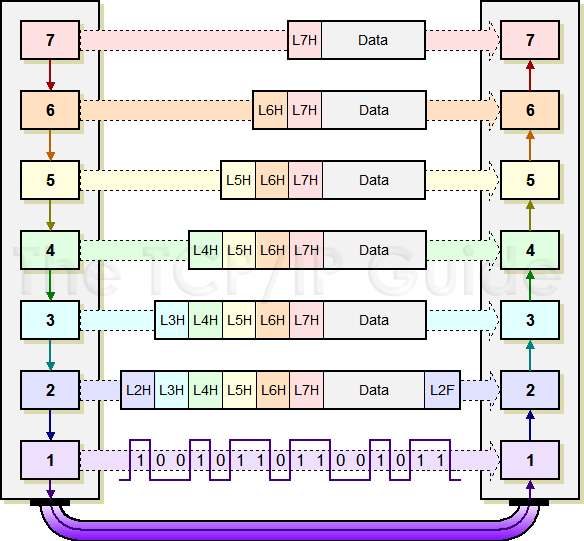
Static entries in the ARP table is done for static routes and requires an administrator to manually enter the IP address, subnet mask, gateway and corresponding Mac address. This requires a manual update each time a route is added, removed or a change is made. Dynamic entries are enabled by the use ARP. When a network is divided into segments, a hub (now obsolete), a bridge or layer 2 switch joins the segments and filters traffic to each of the segments. These devices build their own address table with an exception to a hub which does not build its own address table. A bridge has only Mac address on its table while a switch determines which device is having a said IP address and its corresponding port (which has the Mac address). This is achieved from matching a received response of a broadcast to the port from which the response is received. Eventually the IP address and port number are mapped and entered on the ARP table on the switch. References http://searchnetworking.techtarget.com/definition/Address-Resolution-Protocol-ARP http://www.cisco.com/c/en/us/td/docs/ios-xml/ios/ipaddr_arp/configuration/15-mt/arp-15-mt-book/arp-config-arp.html The Data-Link layer is the OSI layer 2 and its functionality lies in moving data across the physical links in a network. At the layer 2 operations within a network, it is a switch that redirects messages (frames) by using the Media Access Control (MAC) address of the destination device to determine where to direct the message. The Data-Link layer is made up of two sub-layers that are described in the IEEE-802 LAN standards and called Media Access Control (MAC) and Logical Link Control (LLC) The functionalities of the Datalink layer is as follows Media Access Control (MAC): Responsible for the procedures used by devices in controlling access to the network media which may be copper twisted-pair or fibre cables as used in wired networks or radio frequency as used in wireless networks.. Since many networks use a shared medium (such as a single network cable, or a series of cables that are electrically connected into a single virtual medium) it is necessary to have rules for managing the medium to avoid conflicts. For example. Ethernet uses the CSMA/CD method of media access control. Logical Link Control (LLC): Responsible for the establishment and control of logical links between local devices on a network. The Data-Link layer safeguards the initial connection which has been set up, divides output data into data frames, and manages the acknowledgements sent to sender from receiver to indicate that a frame arrived successfully. It also ensures that incoming data has been received successfully by analyzing bit patterns at special places in the frame. Data Framing: Responsible for the last encapsulation of packets received from the network layer which is turned into frames and that sent over the network at the physical layer. Addressing: The address referred to here is a known as MAC address. It is the physical address or hardware address of each device on a network (associated with the network adapter.. The MAC address has 2 parts namely Organizationally Unique Identifier (OUI) and Device ID. The OUI part of any MAC address is unique to the vendor that manufactured that particular brand of device while the device ID is unique to that very particular device. A MAC address is made up of 12 hexadecimal digits, 48bits long and separated by hyphens. It would look something like 00:A0:C9:14:C8:29 or 00-14-22-01-23-45 The OUI for the manufacture of this router is the first three octets—"00-14-22." Below are examples of some manufacturer’s OUI Dell: 00-14-22 Nortel: 00-04-DC Cisco: 00-40-96 Belkin: 00-30-BD The MAC address is used by the protocol of the Datalink layer to ensure that frames intended for a specific device successfully arrive at intended device. Error Detection and Handling: Detection and retransmission of damaged, duplicate, or lost frame, thus adding reliability to physical layer. Access Control: Datalink layer protocols determine which device has control over a link at any given time when two or more devices are attached to the same link. Protocols of the Datalink layer includes but not limited to Address Resolution protocol (ARP), Frame Relay, Point-to-Point (PPP), Multiprotocol Label Switching (MPLS), Spanning Tree Protocol (STP). References http://searchnetworking.techtarget.com/definition/Data-Link-layer http://www.tcpipguide.com/free/t_DataLinkLayerLayer2.htm http://whatismyipaddress.com/mac-address https://people.richland.edu/dkirby/141macaddress.htm The Network layer is the OSI layer 3 and its functionality lies in routing (transferring) network messages from one end device to another. The most popular layer 3 protocols are Ipv4, Ipv6 and ICMP. Its functions include Logical Addressing For the said transfer to occur, the end devices must have a unique address. There are two categories of addresses namely physical address and logical address. I shall limit my discussion to logical addressing in the network layer. The logical address identifies each end device and is also referred to as an IP address. In IPv4, its binary form is 32 bit long and has 4 octets (with 8 bits each) separated by a dot. Its decimal form is 4 numbers each separated by a dot. Each octet range between 0 and 255. 11000000.10100001.11111111.00000001 - Binary 192 . 161 . 255 . 1 - Decimal Each of the 8 bits of each octet has a fixed number from left to right. Each number has its value halved as its next number. This is always constant for each octet from left to right. 128 64 32 16 8 4 2 1 On the other hand, Ipv6 has 128 bits and looks something like 2001:0db8:3c4d:0015:0000:0000:1a2f:1a2b Each address includes a network ID and a host ID for both IPv4 and Ipv6 Routing The transfer of the network messages referred to earlier is actually the routing part of the network layer functions. A layer 3 device such as a router or multilayer switch gets the job to determine where to send incoming packets so as to get them to their final destination. This might have to pass through what is referred to as a default gateway (the entry and exit point of any network traffic that originates from one network but destined for a different network) because the traffic which contains the packets may have to travel through more than one intermediate networks to get to its final destination network. Network protocols are used in this layer, protocols such as OSPF, EIGRP, RIP Data Encapsulation: Message data which is received from the transport layer (layer4) as segments is encapsulated and turned to packets with a network layer header included. 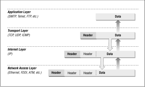 References http://www.tcpipguide.com/free/t_NetworkLayerLayer3.htm http://www.dummies.com/programming/networking/network-basics-the-osi-network-layer/ https://www.interserver.net/tips/kb/types-features-classes-ip-address/ http://docs.oracle.com/cd/E19253-01/816-4554/6maoq01od/index.html http://www.highteck.net/EN/Network/OSI_Network_Layer.html https://docstore.mik.ua/orelly/networking/firewall/ch06_03.htm Moving Data in the Network: PDU, Encapsulation / De-encapsulation  To begin with, this is a quick reminder of our networking protocol stack. The OSI Model/ protocol stack also described by the TCP/ IP Model/ protocol stack has been discussed earlier. However for the sake of this discussion, I will make popular reference to the OSI Model.  Protocol Data Unit (PDU) is the term which describes data as moves through the layers of the OSI model. It consists of protocol control information and user data. Below is a list of what PDU is called per layer of the OSI model
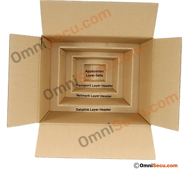
Protocol Encapsulation and De-encapsulation  Encapsulation As data moves from one layer of the TCP/ IP protocol stack to a lower layer at the source, information known as headers is added at each layer to the actual data being sent. The header along with the actual data now becomes the data at the next lower layer as the lower layer’s header is added. This is referred to as encapsulation. It only means that the initial data is encapsulated in a virtual envelope with a header then sent to the next lower layer. On its arrival, the virtual envelope (with the previous header) is repackaged into another new virtual envelope for the current layer and a header for the current layer is added to the new virtual envelope. The process repeats itself until it gets to layer 1 where the envelope is eventually transmitted to its destination. The exception is on layer 2 where not only a header is added but a footer called Trailer is also added. 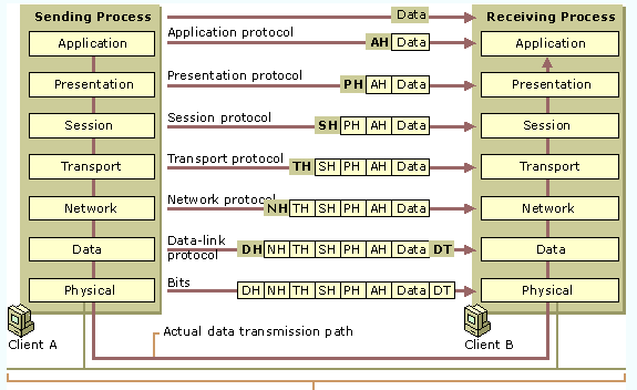 De-encapsulation
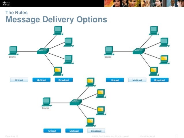
PDUs are labeled for easy direction and re-assembly after De-encapsulation. This allows the PDUs to have order on arrival thus eases re-assembly. On arrival at the destination, the reverse of encapsulation occurs. This is known as De-encapsulation. The virtual envelopes are stripped off and the header helps the process with the information contained in it. This helps the PDU to be delivered to the exact network application awaiting the data. References http://aaronshi.blogspot.ie/2012/11/data-link-layer-add-both-header-and.html https://s-media-cache-ak0.pinimg.com/originals/3e/53/42/3e534245a610e82dd09bf17e5c828c84.jpg http://www.omnisecu.com/images/tcpip/encapsulation-decapsulation-boxes.jpg http://www.omnisecu.com/tcpip/tcpip-encapsulation-decapsulation.php http://www.tcpipguide.com/free/diagrams/osiencap.png http://www.tcpipguide.com/free/t_IPDatagramEncapsulation.htm https://www.techopedia.com/definition/25292/protocol-data-unit-pdu http://www.webopedia.com/TERM/P/PDU.html Messages are delivered via different methods. Sometimes, it may be needful to send information to a single person. This is referred to as a one-to-one delivery and is called unicast which implies that there is only one destination (single destination) for the message being sent. An example in terms of people is a conversation between two people ie only one sender and only one recipient. There may arise a need for a group of recipients to receive the same message simultaneously. This could lead to either of the two options I will be discussing next. It may be needful to communicate information to more than one person, perhaps a group of people (at the same time). This is referred to as one-to-many and is called multicast which implies that one sender to multiple destinations / recipients for the same message being sent. Other times may warrant the information to be communicated to every person in the same area. This is referred to as one-to-all and is called broadcast which implies that one sender sends a message to all connected recipients. References http://paf.dias.ac.cy/main/files/cisco_rs_ite/CCNA-R-S_ITN/course/module3/3.1.1.7/3.1.1.7.html http://www.erg.abdn.ac.uk/users/gorry/course/intro-pages/uni-b-mcast.html https://image.slidesharecdn.com/itninstructorpptchapter3final-141024004736-conversion-gate01/95/ccna-1-routing-and-switching-v50-chapter-3-11-638.jpg?cb=1414112272 Try to imagine if this whole write up appears as one really really long sentence.
"Trytoimagineifthiswholewriteupappearsasonereallyreallylongse ntence". You would find it hard to read and understand. A conversation between two people is usually made up of many smaller sentences instead of having one really long sentence.Smaller sentences make it easier for the message to be received with understanding. These smaller sentences have a limitation of size. The processing ability of the other person (amount of information the other person can process per time) might also be a limitation. In the same wise, when a long message is sent from one host and received at another over a network, it will only make meaning if the message is broken into smaller pieces. This process is known as segmenting. Each segment is encapsulated in a separate frame which has the address information before being sent over the network.There are rigid rules which govern this process as frames which are either too long or too short will not be delivered. It must meet the minimum and maximum size specification. These rules can be different depending on the media through which the message is sent. On arrival at the destination host, the message is de-encapsulated and then reconstructed back into the original message so as to be processed and interpreted. References https://sites.google.com/site/networkingquickwiki/network-protocols-and-communications/message-size  People use timing to determine when to speak, how slow or fast to talk, and how long to wait for a response. The rules bordering message timing include
Access Method Access Method is that rule which determines when someone is able to send a message. The environment is the basis for these timing rules. If normally, you can speak whenever you have something to say, in this environment you have to wait until no other person is talking before you speak. If two people talks at the same time, there will be a collision of information which will necessitate the two parties backing off to start (retransmitting same message) again. This process ensures successful communication. In like manner, it is necessary for computers to determine and define an access method. Hosts on a network need a rule such as access method to know when to start sending a message and how to respond when there is occurrence of error. Flow Control Another timing rule which affects how much information can be sent and the speed that it can be delivered is Flow Control. If person A is trying to communicate with person B and person A talks too fast, it becomes difficult for person B to hear and understand the message. Person B then tells person A to slow down (reduce talking speed). In network communication, a sending host can transmit messages at a faster rate than the destination host can receive and process the message. It is therefore essential for source and destination hosts to use flow control to agree and work out correct timing for successful communication. Response Timeout If person A asks a question from person B and he does not hear a response within an acceptable time frame, person A will assume that no response is coming and so reacts accordingly. Person A may choose to repeat the question again or may go ahead with the conversation. In similar manner, hosts on the network also have rules which determines how long to wait for responses and what action if there is an occurrence of response timeout. References http://networking.xtreemhost.com/wp/?p=287 http://www.netakademija.rs/pdf/ccna%20r&s/01.Introduction%20to%20Networks/ITN_instructorPPT_Chapter3_final.pdf  A message that is sent from source to destination must use a specific format (which implies a design, style or appearance) or structure. A message format will depend on the type of message and the medium through which the message is delivered. For centuries, writing of letters has been one of the most popular forms of style of human communication and for that long, the set format for personal letters has been consistent. A personal letter would incorporate the following components:
Despite this set format, most personal letters must also be encapsulated (contained) in an envelope for delivery. The envelope will have 2 addresses on it – one address for the sender and the other address is for the receiver with each address positioned at the appropriate place on the envelope. If the destination address as well as its formatting are not proper, the letter will not delivered. The process of putting one message format (the letter) inside another message format (the envelope) is called encapsulation. When the process is reversed by the receiver (the letter is removed from the envelope), this is referred to as de-encapsulation. A written letter has an approved and set format to ensure that the letter is delivered and understood by the recipient. In like manner, a message which is sent over a computer network needfully follow specific format rules for it to be delivered and processed. Computer messages are encapsulated in same way a letter is encapsulated in an envelope for delivery. Each encapsulated computer message has a specific format, known as a frame. A frame represents the envelope for the message which is sent over the network. A frame provides the address of the destination host and the sender’s (source host) address. The type of message being sent and the channel over which it is sent determine the format and contents of a frame. Messages that are not correctly formatted will not be successfully delivered to / processed by the destination host. References http://ecovi.uagro.mx/ccna1_en/course/module3/3.1.1.4/3.1.1.4.html http://image.slidesharecdn.com/itninstructorpptchapter3newlesson1-160626171708/95/2-7-638.jpg?cb=1466961674 |
CategoriesAuthor I have a passion for networking and use this medium for tutorials in Networking Archives
April 2017
Categories |
 RSS Feed
